
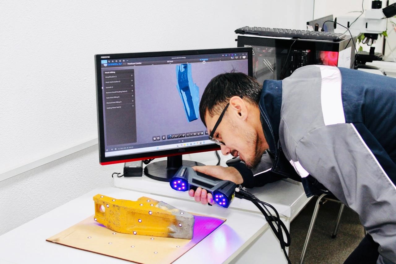
Quality control on a heavy-industry production floor has, for decades, meant a person with a caliper, a go/no-go gauge, and a clipboard. That person is being replaced by a scanner. According to reporting from VoxelMatters, rail manufacturers building everything from high-speed trainsets to metro cars and freight rolling stock are moving inspection off the tape measure and onto non-contact optical metrology systems — hardware built by companies like SHINING 3D, whose metrology scanners capture a full part's surface and compare it directly against the CAD model it was supposed to be. If you have ever scanned a bracket to reverse-engineer it, or laid a printed part over its source mesh to see where it drifted, you already understand the core idea. Industry is just running it at 15-meter scale with 0.004mm accuracy.
What the scanners actually do
The mechanic here is worth stating plainly, because vendor marketing tends to bury it. A metrology-grade 3D scanner captures full-field surface data — not a handful of touch points, but a dense point cloud covering the entire visible geometry of the part. That cloud is then aligned to the part's nominal CAD model, and the software renders the difference as a color deviation map: green where the physical part matches the design, warm colors where it bulges proud of nominal, cool colors where it falls short. A welded seam that has pulled 0.3mm out of alignment shows up as a red streak along the weld. A cast coupler with a sink mark reads as a blue depression. Nobody has to know in advance where to measure.
SHINING 3D's lineup cited in the rail deployments — the FreeScan Trak Nova, FreeScan Trak ProW, FreeScan UE Pro2, and the OptimScan Q series — pushes stated accuracy up to 0.004mm, which is below the resolution most shop-floor contact tools can reliably repeat. The other headline capability is marker-free scanning of large assemblies. Historically, optical scanning large objects meant plastering the surface with reference stickers so the scanner could stitch overlapping frames together. Marker-free capture drops that step, which matters enormously when the "part" is a train car body or a 15-meter section of track turnout.
Why rail, and why now
Rail is a useful proving ground because its parts are simultaneously huge, safety-critical, and geometrically fussy. The VoxelMatters documentation of the deployments reads like a catalog of jobs that manual metrology handles badly:
- Composite nose cones — the aerodynamic fairings on high-speed trains — scanned in roughly 15 minutes without markers, versus the painstaking template-and-feeler-gauge routine a compound-curved composite part would otherwise demand.
- Welded car-body assemblies, where the scanner maps weld-alignment deviation across the structure rather than spot-checking individual joints.
- Two full window assemblies captured in under 30 minutes to trace the source of post-assembly glass deformation — glazing and frames where fit tolerance drives both weatherproofing and safety.
- Couplers and cast components, where inspection time collapses from one to two days down to 30 to 60 minutes. That is the single most dramatic number in the dataset, and it is a throughput story, not just an accuracy story.
- Axles, whose scratches are measured for length, width, and depth within minutes at micron-level resolution — the kind of surface flaw that becomes a fatigue crack, and a fatigue crack that becomes a derailment.
- Turnout assemblies up to 15 meters, scanned marker-free and checked against CAD end to end.
Every one of those benchmarks against the CAD model and outputs a color deviation map. The common thread is that the scanner does not care whether the feature is a 2mm chamfer or a 15m rail section; it captures the whole surface and lets the comparison software find the problems.
The reverse-engineering flip side
Here is where this stops being an industrial-metrology story and becomes a maker story. The exact same capture-and-compare pipeline runs backward. Point a metrology scanner at a part with no CAD model, and the dense surface data becomes the starting point for a reconstructed mesh or a fresh CAD body — reverse engineering, in other words. Point it at a part that does have a model, and you get inspection. The hardware and the scanning motion are identical; only the direction of the comparison changes.
That symmetry is why 3D scanning sits at the front of so many fabrication workflows rather than the back. Before you print a replacement bracket for a discontinued assembly, you scan the original. After you print it, you scan it again and overlay it on the source to verify the copy. Reverse engineering, inspection, and part verification are three names for the same deviation-mapping operation pointed at different reference geometry.
What It Means for Makers
Most readers here are not buying a 0.004mm rail-turnout scanner. But the rail deployments are a preview of where the whole scan-to-CAD toolchain is heading, and several things carry directly down to a print shop or a serious home workshop.
First, marker-free capture is the feature to watch. The reference-sticker workflow is the single most tedious part of prosumer scanning, and its disappearance on industrial hardware signals that the algorithms doing frame-to-frame registration have matured enough to trust geometry alone. That capability trickles down.
Second, the deviation map is the deliverable, not the point cloud. If you are evaluating scanning tools — or building a QC step into your own print pipeline — the question that matters is how cleanly the software aligns a scan to a reference model and visualizes the difference. A raw mesh you have to eyeball is far less useful than a color map that tells you a corner printed 0.4mm shy.
Third, the time savings are the real argument. Cutting a coupler inspection from two days to under an hour is not a precision story; a skilled machinist with the right gauges could hit those tolerances. It is a throughput story — one operator, one pass, whole-part coverage, immediate visual results. For anyone doing small-batch production, that is the economics that make scan-based verification worth setting up, even at a hobbyist scale where the tolerances are looser and the stakes are lower.
The tape measure is not gone from the production floor. But for any part complex enough to have places a caliper can't reach, non-contact scanning has quietly become the default — and the workflow underneath it is the same one already sitting at the front of your print jobs.
